THE "WOODPECKER RUSSIAN
SENT EA1URO.COM by Fernando Fernández de Villegas (EB3EMD)
 the mid-70's at the height of the "Cold War " (period of great political and military tension between the West and the group of countries Communists led by the former Soviet Union), the listeners of radio stations on shortwave and ham radio operators around the world were stunned to an overpowering signal appeared unexpectedly, from an unknown transmitter operating in the shortwave bands. The signal simultaneously covering about 7 or 8-channel broadcasting, or a bandwidth of about 40 kilohertz.
 signal suddenly appeared and moved basically from a high frequency to another much lower and in its downward path through short wave reached even seriously interfere signals broadcast stations shortwave world's greatest power, which gave an idea of \u200b\u200bthe transmission power of this strange radio emission. Occasionally this most potent signal stopped at a band of 40 kHz in the beginning to cast their supersignal for several minutes. The sound itself was transmitted acute rhythmic pounding sound that was perceived by the human ear as being similar to that caused by a woodpecker to peck at the bark of a tree, hence this strange season it is popularly known as the "Bird Russian Woodpecker "(in English "Russian woodpecker "), the name given by radio amateurs.
frequency signals snacking was about 10 times per second. Extraordinarily powerful signal that was emitted between 7 to 19 MHz and affected the broadcasting bands, amateur and utility existing at the frequency range of shortwave, not respecting them, prompting complaints from many worldwide paísesde .
The signal was heard for the first time on July 4, 1976. It is claimed that the latter signals were captured in December 1989 but, occasionally, appeared to have captured news again with the signals in different parts of the globe.
Such was the power of transmission of this station, valued at some of its broadcasts in 10 Megawatts (equivalent isotropic radiated power), which clog up its signal to the most powerful stations short wave radio, and sometimes even could be induced and be heard on telephone circuits (this led to a thriving industry of filters for the woodpecker and circuit noise blockers).
harmonic frequencies of the "Woodpecker" whether the shortwave bands, came to disrupt TV broadcasting in VHF band-I in the years that have not there was cable TV. With the help of military satellites and other special equipment was possible to locate the area from which came "pecking" of the "woodpecker." The maps
the area where the transmitting station was located was designated under the name
"pioneer camp" in the then Soviet Union (USSR), now in Ukraine. Much later, in the decade of 2000, once they overcome the Cold War following the collapse of the former Soviet Union in the early 90's, it became clear that the "Russian Woodpecker" were actually three generations. In 1988, the Federal Research U.S. concluded that the strange radar facility was a new generation of the family of so-called Trans-Horizon Radar (OTH, "Over The Horizon", in English), radar capable of seeing beyond the horizon by use of short waves. This was confirmed after the fall of the Soviet Union and is now known as the Duga-3 system, a system that was part of the network of early warning detection and Soviet intercontinental ballistic missile ABM, and that NATO initially designated Steel Yard. (Note: The Russian word means Arco Duga in Castilian).
was the tense period of the " Cold War" between the Soviet bloc (led by the USSR) and the Western bloc (led by the United States), a period that lasted several decades and in which there was great political tension between states States and the former Soviet Union, with some risk of ending up in a great war between the respective blocks, and so there was some risk of nuclear attack from one block to another long-range ballistic missiles carrying nuclear warheads. It was a time when every nation involved is playing his existence, and this led to development and construction (primarily military in nature) that would otherwise never had seen the light, as is the case at hand.
The Soviets had been working on a system of early warning radar systems for ballistic missile defense shield in the 60's, but most of them were based on radar systems with direct line of sight (short range radar) and were only useful to detect and to intercept possible attacks already underway. None of these systems had the capability to immediately alert the missile launch from enemy territory, which could provide the military the necessary time to analyze the attack and prepare a response before it was too late. At the same time Early detection systems satellite the Soviets were not well developed, and a trans-horizon radar (OTH) on Soviet soil did not have these problems, so that work on trans-horizon radar for this purpose began to develop late of the 60's.
Thus, in these types of radars, as the "woodpecker", it emits a powerful signal to the ionosphere, by successive reflections on this and on the ground (typical mechanism of propagation of short waves over long distances) , can reach long distances, far beyond the horizon. If the signal encounters a change in the ionosphere, may be partly reflected back, returning to a receiver associated with the transmitting station. Thus, the signal on its way, checks for changes in the ionosphere caused by the passage of ballistic missiles. The passage of these in the atmosphere causes called "effect of deionization" in the atmosphere wherever they go there (a fairly high above the ground), and this causes variations in the reflection of radio waves that pass by deionized areas, particularly in the short waves, which being partially reflected back and detected in the receiving computer, could indicate the presence of a ballistic missile in flight from either North America or the continent of Europe.
The first experimental system was the Soviet OTH Duga-1, was built on the outskirts of Mykolaiv, Ukraine, and succeeded in detecting missiles launched from the Baikonur Cosmodrome, located 2500 kilometers east , and known as the launching point for rocket Soviet space race.
This experiment showed that the system was workable, and it was later built in the same place the prototype Duga-2, which managed to detect and track missiles launched from the far east of Siberia and from submarines in the Pacific Ocean and as missiles fired at Novaya Zemlya (an island in the eastern Siberian Arctic). Both systems were pointing to the east and as operating systems fully tested defense of the country. These prototypes operated with a relatively low transmission power, but laid the foundations for the realization of a fully operational OTH, Duga-3 system, which was also built in Ukraine, being constituted by a powerful transmitter and a receiver separated by 60 km. After appearing
these strange and very powerful broadcasting in 1976, a first locations by triangulating the source of the signals allowed to reveal that the signal came from Ukraine. There were confusion about the exact origin of the signals, due to small differences in reports from military sources that locate the source of transmissions at alternative locations in Ukraine and Belarus, Kiev, Minsk, Chernobyl, Gomel and Chernihiv. They all identified the same military detachment, operating a transmitter station a few miles southwest Chernobyl (south of Minsk, northwest of Kiev) and a receiver about 50 miles northeast of Chernobyl (just east of Chernigov, South Gomel). Although unknown to most of the world, NATO knew it existed and referred to this station as Steel Yard.
Meanwhile, in civil matters were thousands of studies and research in the world about the purpose of these powerful signals from the Soviet bloc. The secrecy in the flow of information in the Soviet bloc in the Cold War era was that no one (except within the Western bloc military) knew exactly what these signals. At first it was suspected that it was a station of "jamming" whose mission was to cause harmful interference to radio stations of the Western bloc that could not be heard in the Soviet Union and allied countries, but this theory soon broken when it was found that the Voice of Russia and other Soviet bloc similar stations were affected by interference from the "Woodpecker." Other speculative explanations were offered, indicating that it was a system to interfere with communications between submarines, a climate control system using radio waves or even a massive mind-control attempt by the Soviets, and even a communication system hypothetical aliens.
Amateurs, upset with the heavy interference that caused the transmission of "Woodpecker" when transmitting their bands, they decided to fight trying to interfere their signals by transmitting unmodulated signals synchronized with the pulse signal "Woodpecker" and even created an amateur radio club devoted to it, the Woodpecker Hunting Club (Club of hunters Woodpecker) . But the signals transmitted by radio amateurs seemed to have no effect, and it appeared that GRS Duga-3 system were able to differentiate the waveform of the real transmission Duga-3 system of the waveform of interfering signals transmitted by radio amateurs (they were simply carrying RF pulses).
However, soon suspected that it could deal with a Trans-Horizon Radar (OTH), which was confirmed when after the fall of the Soviet Union, began circulating information about the former Soviet Union. In the early 80's the purpose of the radar signal as the signal began to be obvious enough. In particular, the signal contained a clearly recognizable in each pulse, which was eventually identified as a 31-bit pseudorandom sequence, with a bit width of 100 microseconds, resulting in pulses of 3.1 ms. The bit width of 100 microseconds allowing a resolution of radar tracking of 15 km, since it is the time difference it takes the radar signal to travel to and reflected from an object at that distance. Later, when it appeared a new "Woodpecker" link to the Russian Pacific coast, pointing to the U.S., and covering areas that could not cover the first set, was already very clear that actually it was a trans-horizon radar.
In 1988, the FCC (Federal Communications Commission) conducted a study on the Woodpecker. Analysis data showed that the period between pulses was 90 ms and the station was operating in the frequency range between 7 and 19 Mhz, used a bandwidth of 20 to 40 KHz (typically 40 KHz) transmission and each lasted about 7 minutes. The pulse frequency of the woodpecker was typically 10 Hz, although very occasionally pulsing at 16 Hz and 20
In late 1980, after the publication of the FCC, Woodpecker transmissions became less frequent and in 1989 disappeared completely.
The reasons for the deactivation of the Duga-3 system have not been made public, but a major cause seems to be the strategic shift by the end of the Cold War and the collapse of the Soviet Union in the late 80's. It also could have influenced a lot the success of satellite systems Russian US-KS early detection, which first entered service in early 80's, but it was not until the late 80's when they became a warning system and full detection. The satellite system provided a highly reliable and secure system for early detection, while systems of trans-horizon radar was subject to interference own short wave, in addition to the effectiveness of OTH systems was affected by atmospheric conditions.
also emerged that Duga-3 system actually consisted of two stations "Woodpecker." One of them, the one shown here, was located about 30 km the ill-fated Chernobyl nuclear plant in Ukraine, and is sometimes known as Chernobyl-2 station . The other woodpecker was located in Komsomolsk-na-Amur in Siberia (near the city of Marinska, not far from the Pacific coast and the mouth of the Amur River). According to some reports, this latest installment was discharged in November 1989 and some of its equipment was dismantled.
| Signal "Russian Woodpecker" by interfering station WWVH time (in Hawaii), November 2, 1984. |
Installation of Chernobyl-2 station is permanently disabled, although the antennas are still standing. It is located in the Pripyat River within the exclusion zone of 30 km radioactive contamination around the Chernobyl nuclear power station, near the Ukrainian border with Belarus. Pripyat River, and the city of Chernobyl world infamous charged in connection with the most serious nuclear accident at Chernobyl in 1986, close to the facility. The facilities are not removed, although abandoned (as of 2010), and can be viewed through Google Earth or Google system Internet Map in the following geographical coordinates:
transmitting station: 51 ° 18'19 .06 "N, 30 ° 03'57 .35" E (= 51.3052944 ° N 30.0659306 ° E)
View larger map
Receiving Station: 51 ° 38'15 .98 "N, 30 ° 42'10 .41" E (= 51.6377722 ° N 30.7028917 ° E)
transmitting station fed off the energy produced by one nuclear reactor of the infamous Chernobyl nuclear power plant. Specifically, 10% of the electricity generated by the reactor would be used to feed such an enormous radar. It is said that the construction of this very powerful radio station was invested from 500 to 1500 million dollars, twice what was spent on the construction of the Chernobyl nuclear power plant.
The following pictures show the status of the station (in 2010), are taken from various Internet forums that talk about this season, and part of they are also associated with Google Maps at coordinates indicated for the broadcaster.
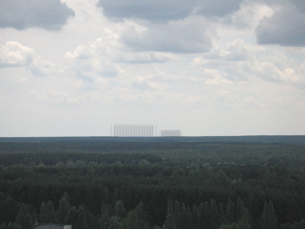
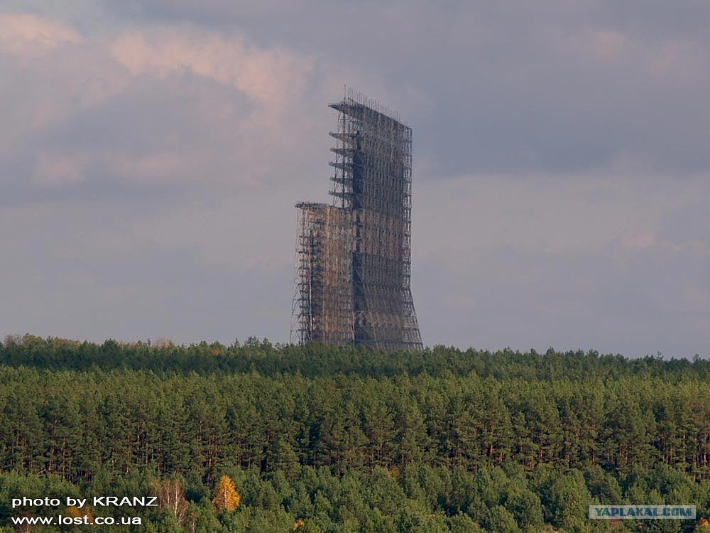
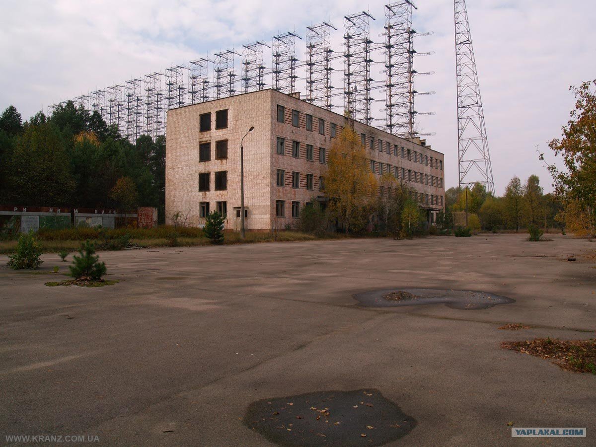
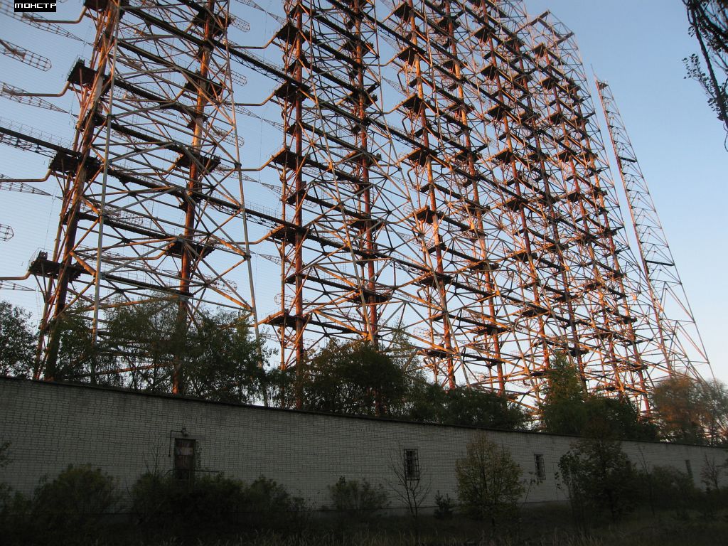
transmitting antenna panels Duga-3 system seen from a distance.
Click on image to enlarge.
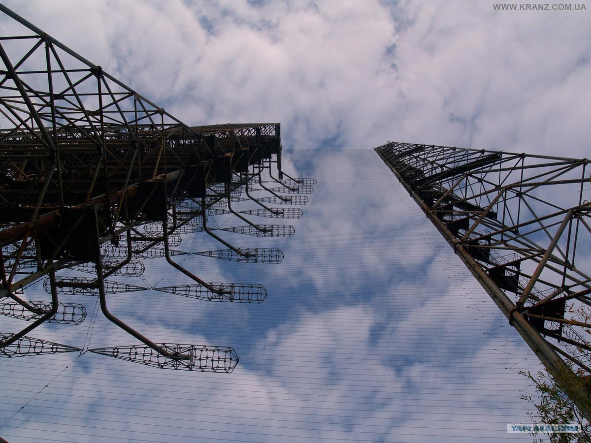
transmission antenna system of the station, seen almost in profile. Click image to enlarge

 Plant
Plant transmitter antennas and buildings.


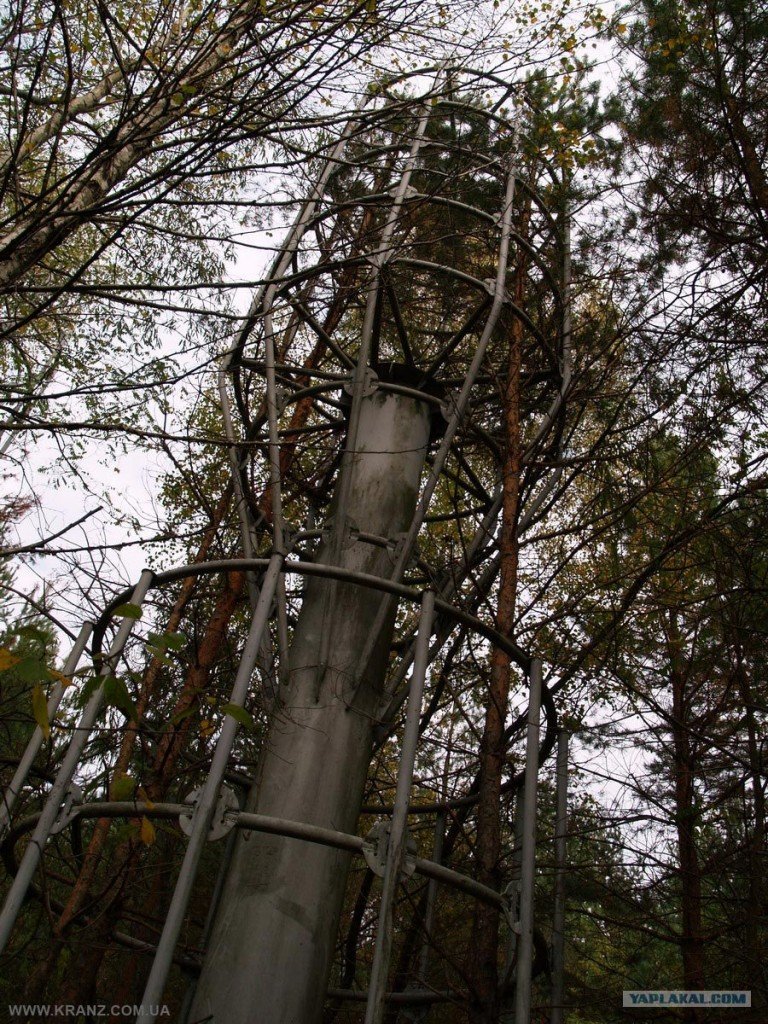
Antennas dipole antenna system for transmission. The system consists of a set of pairs
cylindrical-conical cages encountered (broadband dipole antennas), fed
points faced by a kind of ladder line
suspended for a platform on top of the structure ( visible at the top of the
second image). A reflector panel behind the antenna (left of them) is
made with finer horizontal wires (clearly visible in the bottom center of the image).
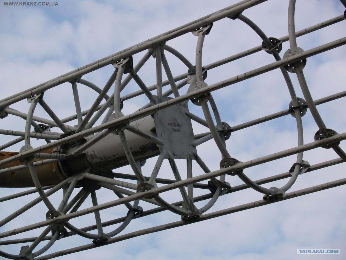
Detail cage antenna. Click on the image to
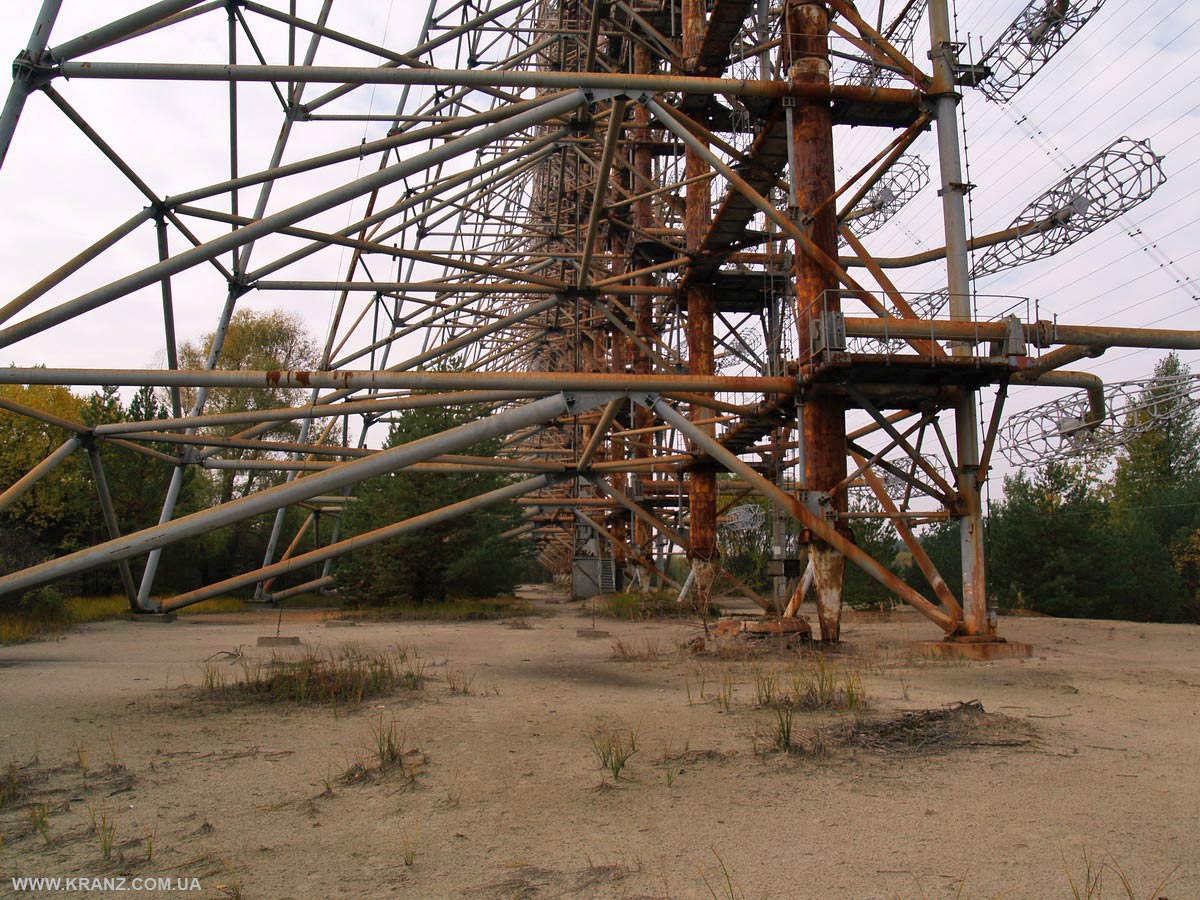
 transmitting antenna
 more, view from the base.
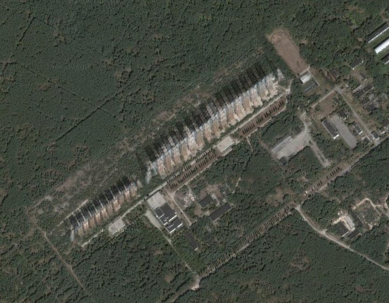
View from satellite broadcaster. Click on image to view
closer transmitting antennas from satellite
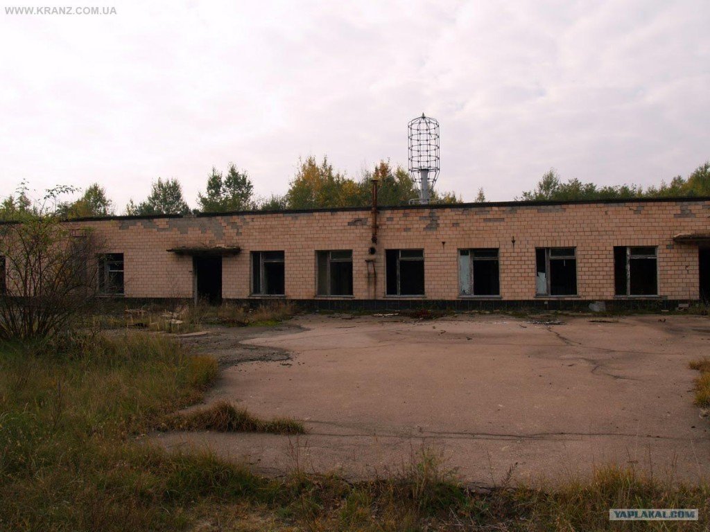
Building ionospheric sounding station. In addition to the transmitting station, the installation included an ionospheric sounding station to check the status of the ionosphere by energy scattered back by ionosphere when it is illuminated by a signal transmission on shortwave. The building is square, about 50 m from the side, and is located about 1400 meters from the transmitting station. The antenna for ionospheric sounding station some distance around the building, with a raised circular lying on the ground around the building. Click image to enlarge.
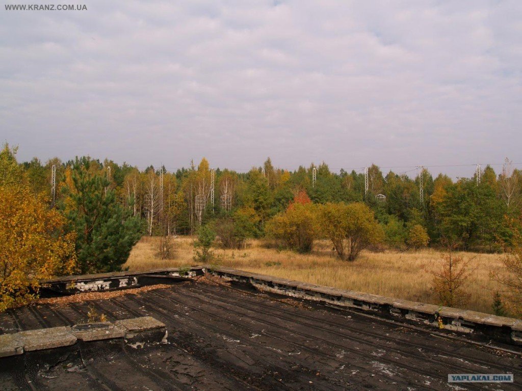
Antennas ionospheric sounding station, almost hidden in the vegetation surrounding the building currently polling station. It consists of a horizontal wire antenna stretched between poles in a circle around the building, and a series of individual antennas conical-cylindrical vertical. The circular perimeter of the antenna system is about 900 meters. Click image to enlarge
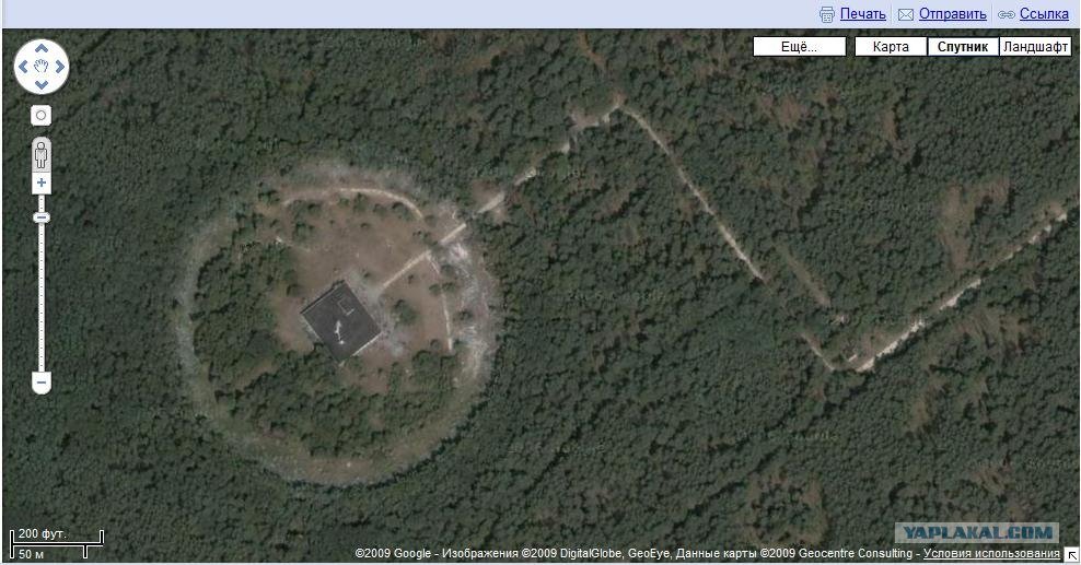
View from satellite (Google Earth) of the ionospheric sounding station. The road to the right connects to the transmission plant, about 1400 meters away. Click image to enlarge.
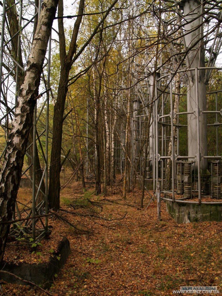
cylindrical antennas ionospheric sounding station. Click on the image para ampliar
Antena cilíndrica de la estación de sondeo ionosférico. Haz clic en la imagen para ampliar
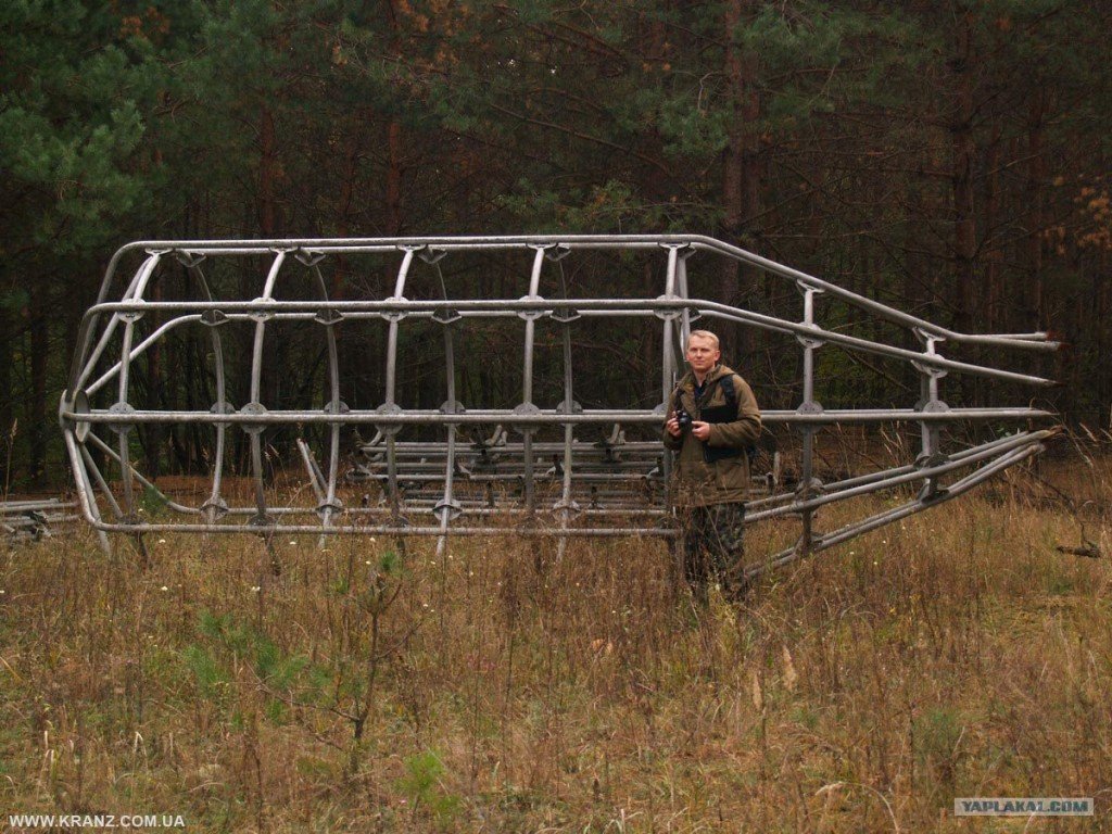
Antena cilíndrica de la estación de sondeo, ya desmantelada.
Observe su tamaño. Haz clic en la imagen para ampliar
Edificio de la estación receptora, junto a la antena receptora. Situada a unos 60 Km
al nordeste de la estación transmisora. Haz clic en la imagen para ampliar
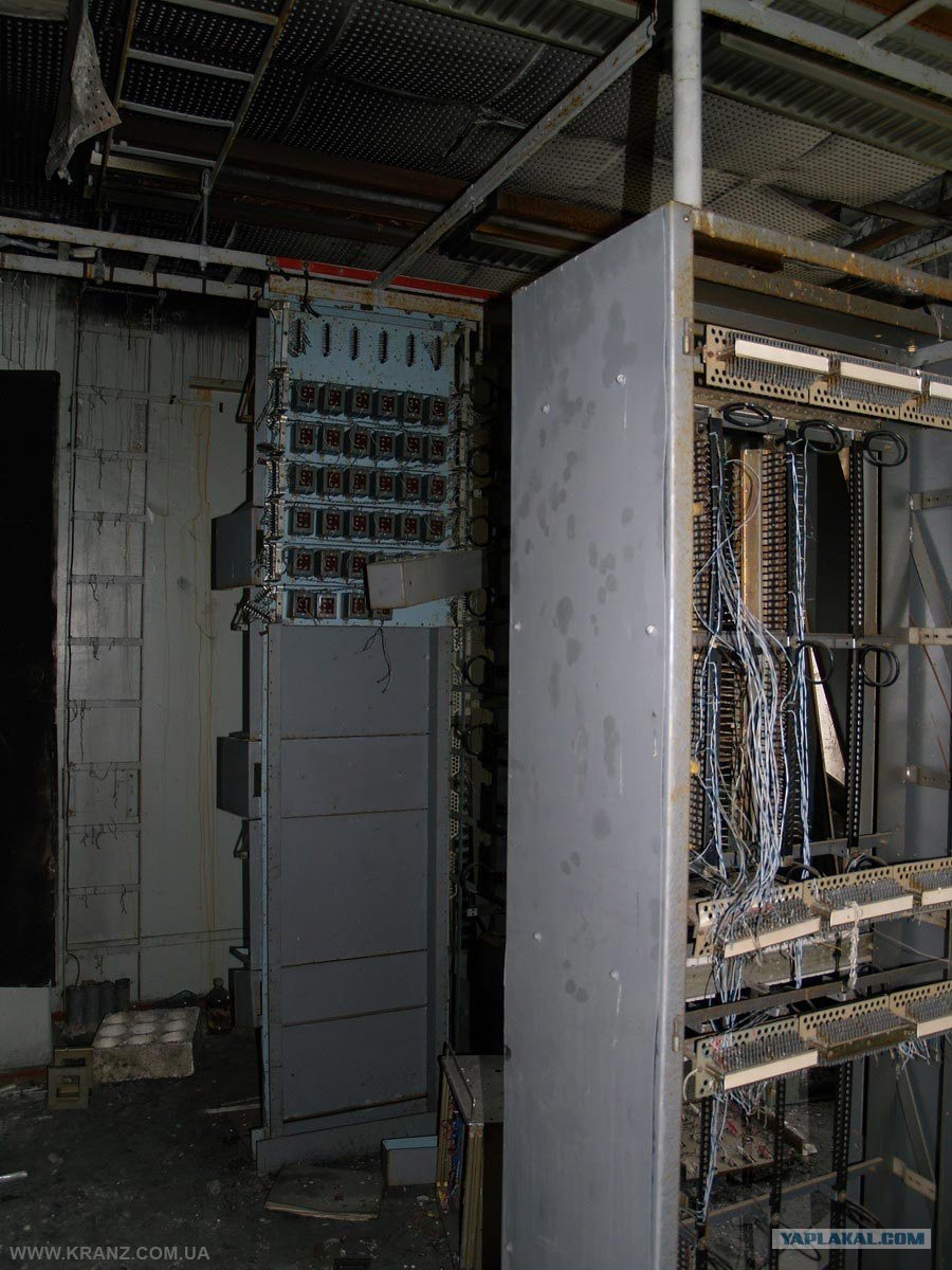
building communications room of the receiving station: terminal
phone circuits. The building also had its roof antennas for satellite communications
. Click image to enlarge.
antenna system of the receiving station, more "discreet" than that of the transmitting station.
Click on image to enlarge.
Dipolos receiving antenna system and attached to the station building. Similar to the system TRANSMISSION antennas can be see the cylindrical-conical dipoles stacked vertically and diagonally, fed by lines in a stepped, with a reflector behind them formed by a number of parallel wires stretched horizontally. Click image to enlarge.
Scaffolding receiving antenna system. Click image to enlarge
Fernando Fernández de Villegas (EB3EMD)
0 comments:
Post a Comment