As Elecraft gets ready to release its KPA500 solid state amplifier, I’ve been comparing similar amps from other manufacturers. According to a recent posting to the Elecraft reflector by Eric Swartz WA6HHQ, the KPA500 will be around $2000 for the kit version.
That’s “kit” as in solderless K3-style. In the meantime, as I (and others) do the age old dollar-to-benefit analysis, it’s interesting to note what’s available as the trend in amplifiers ever so slowly migrates toward solid state.
A few months ago, I purchased my first amplifier ever – a 500W Ameritron AL-811 (tubes). I bought it used and paid 60 cents/watt for it. The additional power has been noticeably beneficial – I’d wondered prior to using it if I’d be able to tell in my normal routine of DXing.
I can.
My original intention when buying it was that I’d use it only on 40 and 80 meters. Wrong!
Several recent DXpeditions have been active on 15 and 17 meters – bands that are only beginning to open, perhaps for a few hours a day. Those DX stations have, at times, been merely a whisper – likely unworkable at 100 watts. To even copy them at all requires all the finesse the K3 is capable of and known for, so the extra power was probably the difference between logging the contact and not.
What I don’t like about the amp is that 1) changing bands requires re-tuning and 2) the T/R relays are as loud and clunky as you’d expect QRO relays to be.
A solid state amp is looking attractive and I’m sure I can sell my AL-811 for what I paid for it.
500 watts makes a real difference over 100 watts. 7 dB mathematically; additional band-countries operationally.


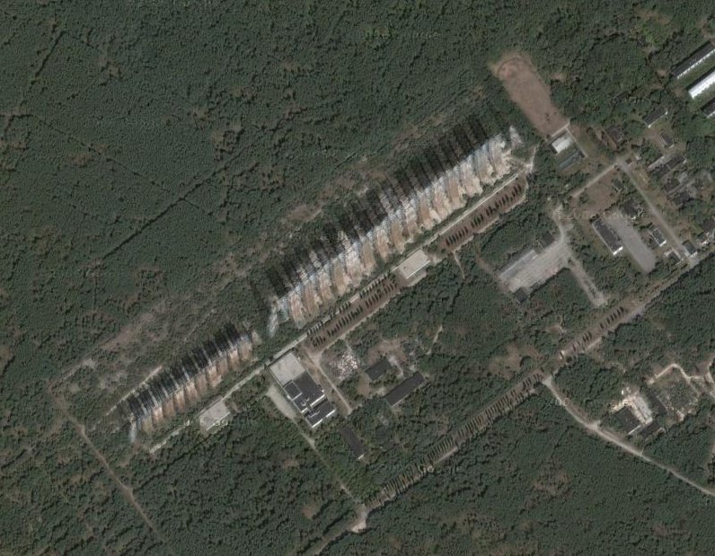
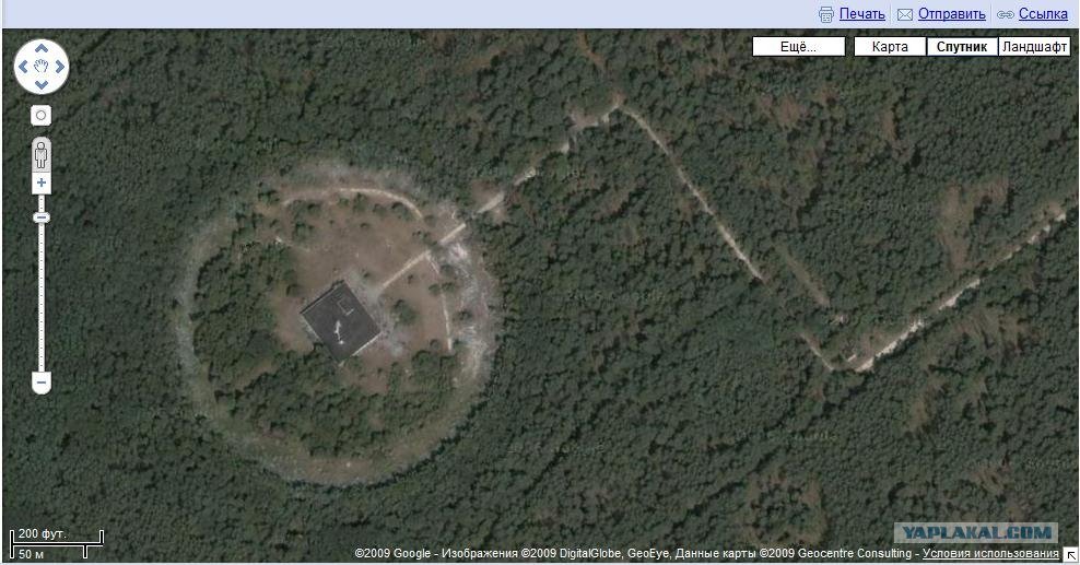
 Plant
Plant 

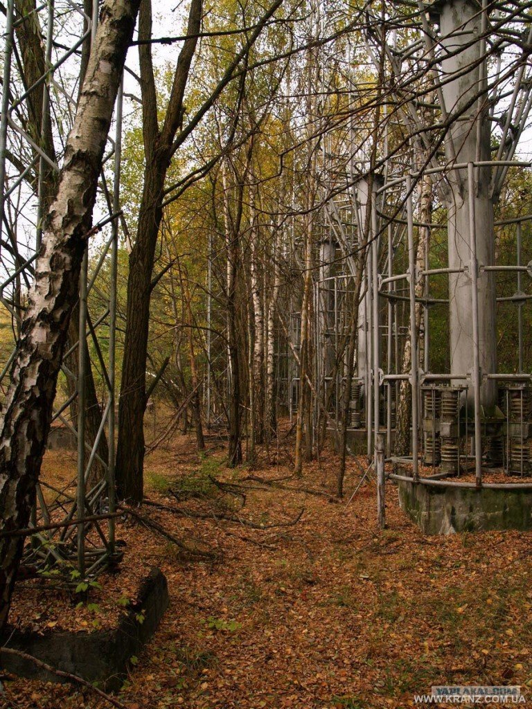
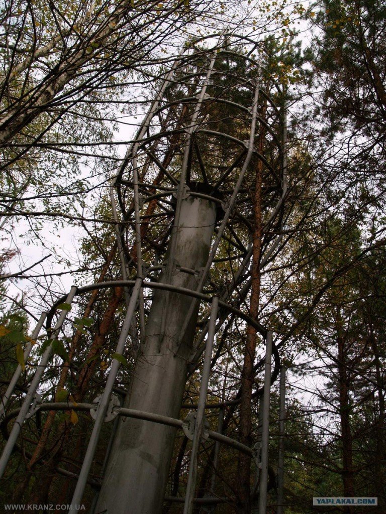
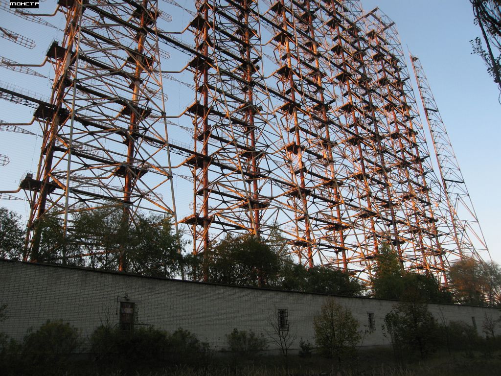
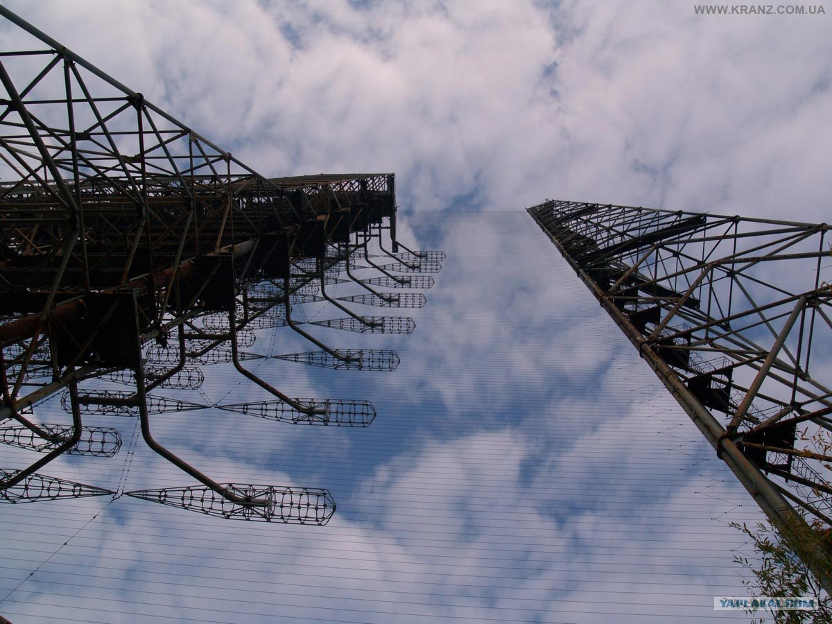
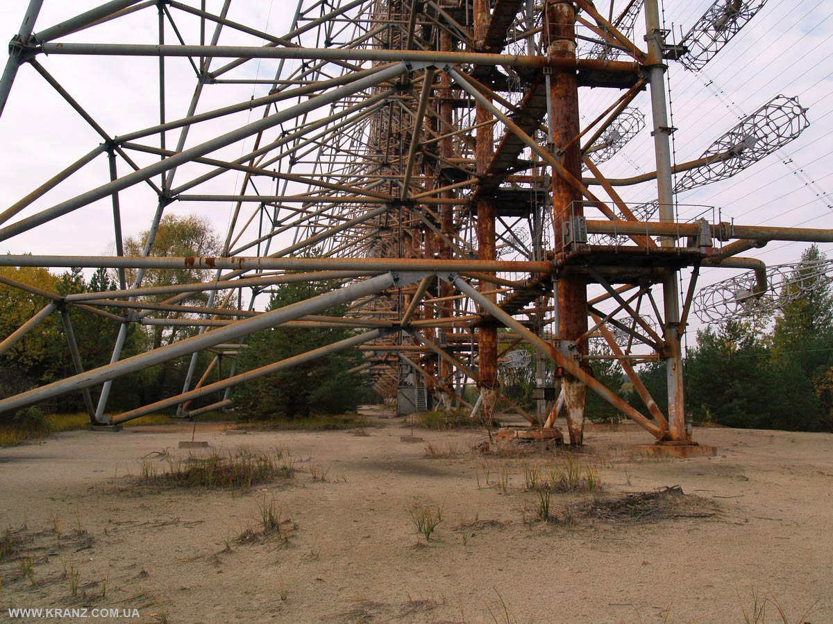
 transmitting antenna